"Geophysical Sensor"
(Return to Index Page)
Preliminary Patent Application
February 27, 1978
Sunnyvale, California
Copyrighted © by The Townsend Brown family. All rights reserved.


This invention relates to the utilization of a recently
discovered so-called "petroelectric" phenomenon.
The as-yet little-understood effect appears as electrical
self-potential signals which are generated within certain high-K
dielectrics, including rocks. These electrical potentials are found to
undergo characteristic diurnal, secular and pulsive variations related to
the geophysical environment.
The invention, therefore, relates to geophysical sensors,
especially portable sensors adapted to field surveys, for determining
certain geophysical parameters useful in prospecting.
The invention relates to sensors useful in geothermal
surveys for determining (remote) temperature gradients or hot spots in
sub-surface rock formations.
The invention relates to sensors useful in earthquake
precursor research.
The invention further relates to basic method and means for
generating electricity.
It has been found that certain dielectric materials, more
particularly those materials having high density (specific gravity) and high
K (dielectric constant) generate an emf spontaneously. Such materials
include many of the conventional dielectrics used in the manufacture of
capacitors, such as mica, glass, oiled paper, ceramic, plastic and
electrolytic film. Certain granitic and basaltic rocks likewise generate
an internal self-potential which can be conducted away by suitably placed
electrodes and leads so as to be utilized. In most natural high-resistance
materials the polarity remains fixed with time, but it has been found that,
in some materials, the polarity occasionally reverses due to some external
influence not as yet clearly identified.
In virtually all cases involving the so-called "petroelectric
effect", the emf is observed to vary substantially with time i.e., engaging
in diurnal or semi-diurnal, secular and pulsive variations which, it is
found, cannot be attributed to internal changes in temperature, pressure or
other purely internal factors within the sensor itself. It has been
established that these variations arise from external causes related, in the
main, to the geophysical environment. Hence, one of the applications is a
sensor for certain geophysical parameters which are otherwise difficult to
observe.
It must be remembered that the geophysical environment giving
rise to factors which affect the petroelectric sensor is remote from the
sensor itself. The physical "mechanism" which connects the two is not, at
this time, clearly understood, but it seems certain that it must be
radioactive in nature. In short, it would appear that the geophysical
environment (air, rock, water, etc.) produces a spectrum of penetrating
radiation which is picked up (thru shielding) by the sensor.
With certain sensors, as described herein, the sensing of
remote temperature is an important feature. The action is similar to that
of a remote-reading pyrometer, except that the connection is not infra-red
but some other form of radiation not presently recognized. This ability to
sense the temperature of remote matter is termed "perithermal".
Practical applications of such a sensor must include, in
combination, means to observe the voltage (or current) fluctuations. Digital
readout meters and/or strip chart recorders are indicated. These are
standard off-the-shelf items which are readily available commercially. A
complete sensing/indicating system, therefore, includes the use of an
indicating or measuring instrument along with a sensor.
For example, a simple system, intended to be covered by this
application for patent, would be merely the combination of a suitable sensor
(such as a capacitor or rock) connected to a millivoltmeter, as set forth
in Figs. 1 & 2.
Such a system, especially the sensor, must be
electrostatically and barometrically shielded and must be held at a
constant temperature, but such peripheral facility, however, does not
necessarily form a part of the following specifications.
Specifications:
Fig. 1 illustrates the simplest form of the invention
consisting of a high capacitance capacitor, such as a 240,000 mfd (Mallory
or equivalent) in combination with a high impedance millivoltmeter.
Fig.2 is similar to Fig. 1 but illustrates a rock (or section
of rock) in place of the capacitor.
Fig. 3 illustrates a slight departure from the above in that
a high power, multi-megohm resistor is connected to a capacitor through a
diode.
Fig. 4 illustrates a plurality of sensors (as in Figs. 1, 2
& 3) in series for the purpose of increasing output voltage.
Fig. 5 illustrates a plurality of sensors (as above) in
parallel for the purpose of increasing current output.
Fig. 6 illustrates sensors as above connected to a useful
load as a power supply.
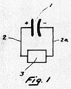
Referring in detail to the attached drawings, Fig. 1
represents the simplest embodiment of the invention, i.e., capacitor 1 is
connected by leads 2 and 2a to a high impedance millivoltmeter 3. This meter
may be a combination pre-amplifier coupled to a suitable readout or
recorder.
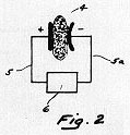
Fig.2 is similar to Fig.1 except that dielectric section 4,
preferably of high density (spec. gravity), high-K (dielectric constant)
material, is substituted for the capacitor. Electrodes are plated on said
dielectric section which are connected by leads 5 and 5a to high impedance
millivoltmeter 6 or equivalent.

Fig. 3 shows a combination of a high power multi-megohm
resistor 7 connected to diode 8 and storage capacitor 9, hence to
millivoltmeter or equivalent. In this configuration, pulsive voltage
variations are generated within resistor 7, which is electromagnetically
and electrostatically shielded within shield 11, thence rectified (if
necessary) by diode 8 and conducted to storage capacitor 9 which is
monitored by readout 10. Tests reveal that the behavior of certain
resistors match that of capacitors and rocks as set forth in Figs. 1 and
2.
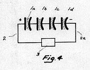
Fig. 4 shows a plurality of capacitors, 1a, 1b, 1c, & 1d as
in Fig. 1, connected by leads 2 and 2a to readout 3, for the purpose of
increasing voltage output and sensitivity.
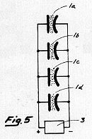
Fig. 5 is similar to Fig. 4 except that capacitors, 1a, 1b,
1c, & 1d are connected in parallel by leads 2 and 2a to readout for the
purpose of increasing current output and sensitivity.
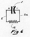
Fig. 6 illustrates the simplest form of power supply wherein
capacitor 1 generates a continuous electrical output which is conducted
by leads 2 and 2a to a useful resistive load 12.
Claims:
1. A geophysical sensor consisting in combination a capacitor
and a voltmeter.
2. A geophysical sensor consisting in combination a rock-like
material capable of generating steady state (current) electricity and a DC
voltmeter.
3. A geophysical sensor consisting in combination a high
resistance, a diode, a capacitor and a DC voltmeter.
4. A sensor in accordance with Claim 1, comprising a plurality
of capacitors in series.
5. A sensor in accordance with Claim 1, comprising a plurality
of capacitors in parallel.
6. An electrical power source consisting of one or more
isolated capacitors in combination with a useful resistive load.
7. An electrical power source consisting of massive high-K
dielectrics free from piezoelectric, pyroelectric or electrochemical
electric output in combination with a useful resistive load.
8. A power source as in Claim 7 consisting of rocks or
rock-like materials.
9. Means for generating (as opposed to storing) current
electricity comprising a large capacitor equipped with terminals and
leads.
10. Means for generating direct current electricity comprising
rocks or rock-like materials free from piezoelectric, pyroelectric or
electrochemical energy excitation and equipped with terminals and leads to
conduct said current to a useful resistive load.
11. A geophysical sensor comprising the combination with
electrical indicating means, of a plurality of sections of rock-like
materials free from piezoelectric, pyroelectric or electrochemical energy
excitation
12. A sensor according to Claim 2 consisting of heavy
dielectric material such as barium titanate or lead zirconate titanate.
13. Method of generating sustained-current (DC) electricity
beyond that obtained from piezoelectric, charged electret, pyroelectric or
electrochemical sources, consisting in utilizing dielectric material,
attaching electrodes to said material, and conducting away the charges
developed on said electrodes by said material.
14. Method in accordance with Claim 13 wherein the dielectric
material comprises slabs or sections of rocks.
15. Method in accordance with Claim 13 wherein the dielectric
material comprises the dielectric of a capacitor.
16. Method for measuring remote geophysical parameters
consisting in employing dielectric materials, attaching electrodes to said
materials and utilizing the self-potential signals developed by said
materials to actuate measuring instruments.
17. Method in accordance with Claim 16 for detecting
geothermal reservoirs.
18. Method in accordance with Claim 16 for detecting remote
sources of heat.


Please be advised that this document is copyrighted © by The Townsend Brown family. All rights reserved.
Please see Legal and Copyright Information for additional copyright information.
