"Plasma Dynamic Loudspeaker"
(Return to Index Page)
Thomas Townsend Brown
1001 3rd Street
Santa Monica, CA 90403
Copyrighted © by The Townsend Brown family. All rights reserved.


Comments:
The invention described herein is based on the recent discovery by the applicant in "Corona
Dynamics" and relates specifically to the generation and transmission of pressure waves from an
electric coronal discharge to the ambient air. It departs from the applicant's earlier loudspeaker inventions in several significant respects.
In the applicant's earlier transducer patents, the emphasis was placed upon the aerodynamic
forces developed within divergent electrostatic fields. These V-shaped fields are developed
relative to electrodes of special configuration, usually from single fine wires towards sets of
vanes resembling a "venetian blind." Stresses are developed in the air (as a dialectic medium)
which cause the air to flow generally in the direction of the divergence of the field, i.e.,
from the fine wires toward the leading edges of the vanes. Hence, the total pressure and earlier inventions is attributable to:
The combination of the above two electrokinetic forces cause a substantial airflow and the electrode structure acts as a fan. By modulating the applied electric field, a valving action is obtained, and pulses of air are produced. These pulses are sound waves.
In the present patent application, applicant is shifting the emphasis to the plasma dynamics of the corona itself. In other words, the expansion of the coronal envelope around the fine wire anodes (by increasing the electrical potential thereon) creates a pressure wave in the surrounding (air) medium. This is called "corona pressure."
Classical physics describes corona pressure as resulting from thermal expansion of the ionized
gas (including the momentum of outgoing ions), and the energy is represented as the I
2R loss in the coronal envelope.
Such explanation, based solely on upon thermal expansion (and constraction) would necessarily
introduce considerations of ion-transit time and thermal inertia. Those factors would cause an
increase in response time and limit any corona-acoustical radiation to relatively low
frequencies.
Plasma-dynamic speakers of the type referred to in this application are not so limited, and proof of high-frequency operability may be required by the Examiner. As a matter of fact, speakers of this type are found to be extraordinarily effective and efficient even in the ultrasonic range.
It follows, from empirical evidence, that a variation in the density of corona plasma is transmitted to the ambient medium without time lag, and this transmission cannot be due entirely to thermokinetic expansion and contraction of the plasma envelope as presently accepted theory would require.
Regardless of the theory by which sound is produced in the present invention, applicant has found that a loudspeaker built along the lines suggested in the following specifications is remarkably effective. Such a loudspeaker has smooth, highly-compliant response throughout the entire audio frequency spectrum and into the high ultrasonic range. Plasma dynamic speakers are entirely free from inertial and/or Doppler distortion found in all diaphragm speakers.
The novel feature of the present invention, around which claims are largely directed, is the use of the cathodic chamber or "cell," which serves to confine the acoustical energy momentarily, while it is being emitted in the corona. The result is an in-phase amplification of the acoustical energy somewhat analogous to the amplification of light energy within a LASER (See reference D).
In short, the essential feature of the present invention is the confinement (within a compartment) of plasma-generated sound for sufficient time to permit sonic "in-phase reinforcement" of coronal intensity.
The compartments, (cathodicc cells) referred to herein may be described as metallic enclosures open at one end. Sound energy from the enclosed emitters is built up in the cells and emission takes place on the open end. A large loudspeaker is made up of a plurality of such cells with enclosed emitters electrically connected in parallel.
The present invention differs from the applicant's earlier disclosure in the following respects:
It is an object of the present invention to provide an electrokinetic transducer, loudspeaker or the like for the conversion of electrical energy into accoustical energy.
Another object of the invention is to provide a loudspeaker, which is responsive throughout the entire audio frequency range and extending well into the ultrasonic range, entirely free from inertial and/or Doppler distortion.
Another object of the invention is to provide a loudspeaker with self-amplifying in-phase augmentation of sound energy.
Another object of the invention is to provide a loudspeaker, which can be assembled to any required size by adding modules or units.
Still another object of the invention is to provide an electrokinetic loudspeaker, which confines its produced ozone and causes no net airflow.
There are basic differences beyond the teachings of the applicant's earlier inventions. These differences, in part, are brought out in the following:
Referring to the Attached Drawings:
Fig. 1 illustrates the simplest form of the invention. It is a sectional view through the center of a single cathodic cell, together with a diagram of the associated circuitry.
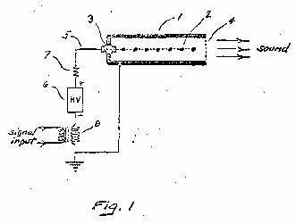
Fig. 2 is a prospective view of cathodic cells in parallel constituting the modules of a larger loudspeaker together with associated circuitry.
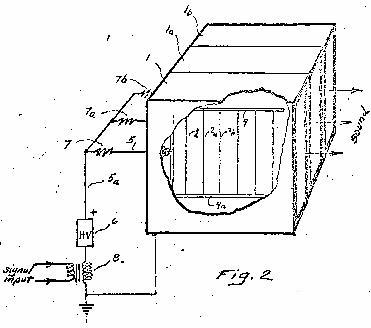
Fig 3 illustrates an alternative form of the invention wherin the cathodic cell is circular in cross-section, the periphery of which is an apertured surface through which sound is emitted from the cathodic cell.
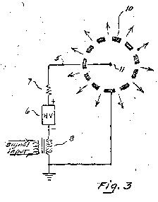
Fig. 4 is a perspective of a tube-like or "cable" speaker representing an elongated form of the cathodic cell illustrated in Fig. 3.
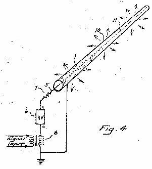
Fig. 5 is a sectional view of a cathodic cell, similar to that shown in Fig. 1 with modulating circuit employing a vacuum tube rather than a transformer.
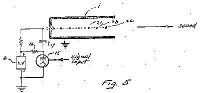
Fig. 6 is similar to Fig. 5 except that a third element, operating as a control grid, is interspersed in a common plane with the emitters.
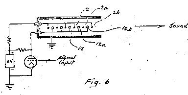
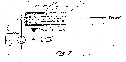
Fig. 7 is an alternative arrangement to that represented in Fig. 6 wherein control grids enclose or are placed at the sides of centrally located emitters.
 Referring in Detail to the Attached Drawings
:
Fig. 1 illustrates the rectangular form of the electrically-conducting enclosure or so-called "cathodic cell" within which sound is generated from electrical signals. Since the walls (1) of the cell must be electrically conducting the cell may be conveniently formed of metal. The cell is open at one end so as to provide an orifice through which the generated sound is propagated to the open air. This orifice is covered by sound permeable cloth (4) which serves to confine the ionization within the cell and prevent the ozone generated therein from reaching the open air. Advantageously, this cloth may contain catalytic agents, such as sintered metal powders for decomposing any ozone which may come in contact, thereby further insuring ozone containment within the cell.
A planar array of electrodes (2) consisting of a plurality of equally spaced fine wires approximately .002" diameter, is positioned in the center along the longitudinal axis of the cell so that the distance between successive parallel wires forming the grid of the array is approximately the same as the distance from the wires and metallic walls of the chamber. Planar array (2) constitutes the anode of the device, and it is connected to the source of high-voltage (6) by means of conductor (5) through insulated pushing (3) through protective resistor (7). The negative side of high-voltage power supply (6) is connected to the secondary of modulation transformer (8) and thence to the ground. The wall of chamber(1) is also grounded, but it is negative with respect to the fine-wire grid in operation, power supply (6) provides high-voltage direct current, usually 10 to 20 KV to the fine-wire grid (2). The resulting positive corona around these fine wires takes the form of a smooth, slightly luminous envelope extending outward from the surface of the fine wires. Approximately 1/164 of an inch in all directions. It is not in an arc. Under pure DC excitation, this luminous envelope is silent; but when the high-voltage is modulated, as by a signal entering the primary transformer (8), sound is generated by the corona around the fine-wire emitters which travels outward and is reflected by the walls of the cell so as to return and concentrate again upon the plasma source. The result is a regeneration of the sound energy within the cell by successive emission and the re-emission occurring within and from the coronal envelope.
Sound energy appears to be added and in-phase reinforcement takes place as the sound waves travel successively from emitter to emitter toward the orifice of the cell. This amplifying action has been described at length in the paragraphs above.
While the structure and circuitry shown in Fig. 1 specifically describes electrode (2) as the anode, it must be understood that operation is possible also with reverse polarity under certain special conditions. An example of a special condition follows the use of electrode coatings to improve or alter the emissive characteristics. For example, fine wires may be coated with thorium oxide, alkali metals for the material of low work function, to facilitate evaporation of electrons.
In this event, certain advantages are derived by using reverse polarity or even RF excitation. It is to be pointed out however, that RF excitation is not entirely satisfactory or desirable for the reason that excessive heating and arcing usually results, and furthermore, the use of RF produces the possibility of radio interference which is highly objectionable.
Fig. 2 illustrates an assemblage of three cells or units connected in parallel. Metal containers (1), (1a), and (1b) represents the individual cathodic cells. The cut-away portion of contain (1) shows grid frame (9) and (9a) supporting parallel emitter wires to (2), (2a), (2b), etc., positioned along the central axis of the cell and connected through insulated pushing (3) by conductor (5) through protective resistor (7) to bus (5a) which is energized by power supply (6). Modulation transformer (8) is used to convert the signal input into variations in voltage supply to bus (5a) and metallic cases of all chambers are grounded.
The modular construction, illustrated in Fig. 2 permits building the loudspeaker to any desired size. Sound-permeable cloth not shown in Fig. 2 is applied over the entire front of the assemblage of modules to provide a unified appearance.
Fig. 3 describes an alternative form of the invention. This embodiment shows the cathodic cell as circular in cross-section and cylindrical in shape. The walls (10) of the cell are perforated so that the sound waves pass through the perforation's (as indicated by the arrows). In this form of cathodic cell, the sound waves are generated in the coaxial coronal envelope around centrally-located metallic filament (11).
Sound regeneration takes place through coencentric reflections within the chamber and the sound waves move outward radially. Emitter (11) is connected by lead (5) through resistor (7) and energized from power supply (6) to modulator (8) as in the previous figures.
Fig. 4 is a perspective of the tube or cable speaker. Tubes may be connected together to form a speaker of indefinite length, where flexibility is required so that the cable may be bent around corners. The fine wire is held in its coaxial location by spacers (not shown) in a manner well-known in the coaxial cable art. Such a cable speaker is covered by sound permeable cloth for the containment of ozonea, as previously described.
Fig. 5 is similar to Fig. 1, except that emitters (2a), (2b), (2c), etc., are modulated from the plate circuit of vacuum tube (15) rather than through the use of the modulation transformer as set forth in the former figures. In the representative circuit illustrated herein, the plate voltage of the tube is supplied through resistor (16) from power supply (6) and the modulation voltage is conducted to the anodic emitters makers (2a), (2b), (2c), etc. through capacitor (17).
Fig. 6 is similar to Fig. 5 except that an array of rods (12), (12a), (12b), etc., positioned midway between emitters (2a), (2b), (2c), etc., and in the same plane therewith, serves as a control grid to influence the space charge around the emitters. This control grid is modulated from the plate of the vacuum tube as indicated.
Fig. 7 illustrates a circuit producing essentially the same result as that shown in FIg. 6 that includes the use of two control grids, (13a), (13b), (13c), etc. and (14a), (14b), (14c), etc., located in the spaces at the sides of or surrounding the emitters (2a), (2b), (2c), etc. These two control grids are electrically connected together and energized from the plate of the vacuum tube as indicated. For the sake of simplicity the input signal is merely shown as being conducted in the conventional way to the grid of the vacuum tube.
Modulation circuits utilizing control grids are valuable and useful in the present invention. The use of the control grid in a related manner is covered in the applicant's co-peending Docket No. 8308, and the teaching is to be repeated in the present specification. The patentable material represented in this application is probably limited largely to the novelty of the cathodic cell and operational improvement, which it provides over the applicant's former loudspeaker patents.
I Claim:
1) Method of converting electrical signals into sound waves comprising confining corona from a highly-charged electrode within an electrically-conducting enclosure, completely closing said enclosure except for the orifice through which the sound generated therein is propagated externally, charging said electrode with respect to said enclosure so as to cause corona and varying the charge thereon so as to produce sound waves.
2) An electroacoustic transducer comprising a plurality of corona emitting electrodes and electrically-conducting enclosure for said electrodes, which is complete except for the sound propagating orifice, means to supply high potential to said electrodes relative to said enclosure, and means to vary said potential according to a signal input.
3) A loudspeaker comprising a plurality of electrically-conducting enclosures open at one end, grids of corona emissive wires within said enclosures, means to supply high potential to said grids, and means to modulate said potential according to input signals.
4) A loudspeaker according to Claim 3, including sound permeable cloth to cover the openings in said enclosures.
5) Cloth, according to Claim 4 impregnated with catalytic materials to decompose ozone.
6) A loudspeaker according to Claim 3, including corona emissive wires coated with materials to increase the emissivity thereof.
7) A loudspeaker,according to Claim 3, including enclosures the inner surfaces of which are coated with materials to increase negative emissivity.
8) A loudspeaker according to Claim 3, including control grids for modulating the electric field in the region of said corona emissive wires.


Please be advised that this document is copyrighted © by The Townsend Brown family. All rights reserved.
Please see Legal and Copyright Information for additional copyright information.
