"The Fluid Pump"
(Return to Index Page)
For the Whitehall-Rand Group, Washington, D.C.
Published in Psychic Observer, Vol. XXXVII, No. 1


In the past, numerous types of devices have been employed to
pump fluid. However, these prior devices are characterized by moving parts.
I have discovered that fluids, and particularly dielectric fluids, may be
pumped by a device which does not require ... that electrical energy may be
converted directly into kinetic energy in the form of moving dielectric
fluids. Accordingly, this device may be employed to pump dielectric fluids
such as air, oil, gases or dielectric solids suspended in a gas through the
system. These propulsive forces are brought to bear upon the dielectric
fluid due to the unique geometry of the electric fields. These electric
fields may be shaped in a manner to produce a propulsive force on the fluid
dielectric by the geometry of the electrodes and by the manner of their
orientation. Further shaping of the electric field may be implemented by
means of the particular mode of energization of the electrodes.
Fluid pumps, in accordance with this invention, may be used
for electrohydrodynamic pumping of oil or other dielectric fluids. They may
be used to produce steady and noiseless propulsion or pumping of air or
other gases. They may also be used for rapid pulsing or pumping of residual
gas in ultra-high vacuum systems. The use of electrical fields to produce a
pumping action is peculiarly adapted to vacuum pumping. Electrical breakdown
rarely occurs in a vacuum and no important limitation exists as to electrode
spacing. Accordingly, very intense electric fields may be utilized, which
fields, when properly "shaped," cause the molecules of the residual gas to
be accelerated to very high velocities. Electrode structures employed to
pump or propel fluids may be serially positioned to be produce a high
measure of vacuum. For example, these electrodes might be positioned in a
manner to produce pressures of the order of 10
-9 to
10
-13 mm of mercury, all without use of moving points.
 Figure 1
The pump consists of two basic parts, a ball
electrode 1 and an annular ring electrode 2. Ball electrode 1 is located on
the axis of the ring electrode and to one side of the plane of the ring
electrode. Electrodes 1 and 2 are maintained at different electrical
potentials by means of conductors 3 and 4 connected to a source of high
voltage 5. Reversal of polarity makes little difference upon the magnitude
or direction of forces developed in the surrounding fluid medium. One or the
other of the electrodes may be grounded if convenient. It has been found
that generally better results are obtained if the ball or point electrode 1
is negatively charged with respect to ring electrode 2 for the reason that
the breakdown potential is higher; hence, higher voltages may be used
continuously. When electrodes 1 and 2 are differently charged, the
dielectric fluid medium near the axis between the electrodes is set in
motion and flows through the ring electrode, creating a steady stream in a
direction indicated by the arrows.
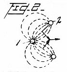 Figure 2
A sectional view in elevation of Figure 1, showing the
configuration, in dotted lines, of the electrostatic lines of force and the
way in which they diverge from the ball toward the ring. Such divergence is
believed to give rise to a resultant pressure on the dielectric medium in
the region principally along the axis between the electrodes generally in
the direction of the divergence. This pressure causes the medium to move
axially through the ring electrode as indicated by the
arrows.
 Figure 3
Electrode 1 is replaced by a tube or annular electrode 6 where
a fluid medium is free to move into the tube from the left, and out of the
tube to the right. For the reasons already set forth, a field exists in the
region between the two electrodes, pulling the surrounding medium through
the electrode 6 along the axis and through the ring electrode 2 and
outwardly, as shown.
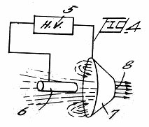 Figure 4
The annular electrode is in the form of a truncated conic or
frusto-conical electrode 7 having aperture 8 of slightly larger diameter
than tube electrode 6. As in the other structures, flow is initiated in the
region between the electrodes and is projected through the aperture of the
conic electrode. The advantage of the conically-shaped electrode over that
of the ring is an increased concentration of electrostatic field between the
electrodes while at the same time preserving the necessary divergence of the
lines of force.
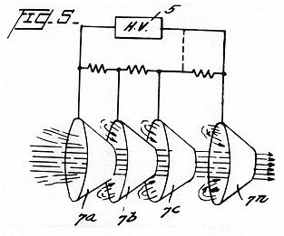 Figure 5
A series of annular frusto-conical electrodes 7a, 7b, 7c...7n
is serially connected to the source 5, by means of voltage dividers. Here,
as in the previous structures, the electric field between successive conic
electrodes is divergent. Hence, a resultant force exists upon the dielectric
medium generally in the vicinity of the axis of the electrodes tending to
drive the medium through the conic electrodes from the larger to the smaller
apertures, as shown.
When the system of conic electrodes is tightly enclosed in an
insulated tube there is a notable difference in hydrostatic pressure between
the inlet and outlet ends of the system, it will also exhibit a force in the
same direction as the fluid flow. Small chunks of matter and even powdered
materials suspended in a dielectric fluid are similarly driven through the
system at high velocity so that, especially in a vacuum, the structure
serves as a linear accelerator.
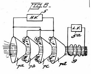 Figure 6
The electrode structure here is the same as in the preceding
figure, except that the electrical connections are in parallel groups rather
than in series. in this structure, successive conic electrodes are of
opposite polarity. It has been found that the desired pumping action can be
achieved with either series or parallel connection but that the parallel
connection offers one advantage, namely, operation of the electrode system
at a much lower voltage.
In Figures 5 and 6 four electrodes are shown. However, it is
understood that any desired number may be employed depending on the amount
of pressure to be produced.
In any of the embodiments shown, magnetic collimation may be
achieved by connecting a solenoid 9 shown in Figure 6, to the source 5a and
orienting solenoid adjacent the last of the electrodes (7d in Figure 6 or 7n
in Figure 5) with the solenoid axis coincident with the electrode axis.
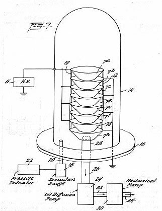 Figure 7
A pump for use in obtaining ultra-high vacuum. For the sake of
convenience, the conic electrodes 7a - 7n are arranged in vertical assembly
by means of insulating cylinder 10 within an insulating tube, 14, which is
supported on base 16. An ionization gauge 18 is connected through tube 20
to the interior of tube 14 and a pressure indicator 22 is operatively
connected to gauge 18.
An oil diffusion pump 24 of the type well known in the art is
connected to the interior of tube 14 by means of a pipe 26 connected to base
plate 16 at an aperture 28. A mechanical pump 30 is connected to the pump
24 by means of pipe and exhausts to the atmosphere through pipe 34. Pumps
24 and 30 merely perform the initial pump-down and the electrohydrodynamic
pump is employed to produce the very high vacuum. Gas molecules are ejected
directly into the oil diffusion pump and exhausted into the atmosphere as
shown.
Since very high voltage can be applied to the electrodes in
vacuum without danger of breakdown, and since the pumping action is roughly
proportional to the square of the applied voltage, the operation of the
system at high voltage for the removal of residual gas is particularly
rapid.
While I have shown and described various embodiments of my
invention, it is understood that the principles thereof may be extended to
many and varied types of machines and apparatus. The invention, therefore,
is not to be limited to the details illustrated and described herein.
