"Plasma Dynamic Microphones"
(Return to Index Page)
Preliminary Patent Application
Docket No. 8310
Thomas Townsend Brown
1236 Chestnut Street
San Francisco, Calif. 94109
Copyrighted © by The Townsend Brown family. All rights reserved.


Description:
This invention is based on a well-known but virtually unused principle in physics whereby the
electrical energy required to maintain a plasma envelope around a highly-charged electrode
varies with the ambient gas pressure upon the envelope. In other words, changing the ambient
pressure upon the corona around a discharging point changes the current necessary to maintain
that coronas. Several factors are responsible for this inter-relation.
The net result is that any corona-emitting point acts as a sensor for the ambient gas
pressure.
Sound waves, of course, use pressure variations. Hence, if sound is concentrated, as by a
parabolic reflector, upon a sensor located at the focus, proportionate changes are produced in
the charging current. If suitable means are provided for amplifying these charging currents,
the structure serves as a microphone.
Such a pressure-sensing electrode structure has the advantage over all conventional microphones
in that no moving diaphragm or other moving mechanical part is required. The freedom from
inertia permits a frequency response presently estimated to extend from a few cycles per second
to well over 250 KC per second smoothly thruout the entire frequency range and without resonance
peaks.
The microphone system referred to herein takes the form of a parabolic reflector or the like,
a highly-charged probe at the focus of said reflector and means whereby variations in an
otherwise steady charging current are amplified and utilized as the output signal.
It has been found that positive corona is to be preferred in most cases over negative corona,
but this depends upon the temperature of the probe and the nature of the emissive coatings
thereon. In certain cases, it is desirable to operate the highly-charged probe at high
temperature, the heat being supplied by an internal resistance unit or by making the probe in
the form of an incandescent filament.
In certain cases, emission is facilitated by fabricating the probe of radioactive material or
by coating the probe with cesium or barium chloride or thorium oxide in order to increase its
emissivity.
Suggested Specifications:
1) This invention relates to microphones, transducers or the like, for converting sound energy
into electrical signals.
2) This invention relates to pressure-sensing devices, especially for rapid changes in gas
pressure.
3) This invention features a microphone without diaphragm or other moving mechanical part.
4) This invention features a high-fideliy microphone, which can be made highly directional so that it is
telescopic in pick-up capability and resolution.
5) This invention features a high-fidelity microphone, free from inertial and Doppler
distortion.
6) This invention features an ultra-sonic microphone with pick-up capability believed to extend
beyond 250 KC per second.
Referring to the Attached Drawings:
Referring in more Detail to the Attached Drawings:
Fig. 1 illustrates a parabolic reflector 1 used to concentrate incoming sound (as shown by the
arrows) into a focal spot where pressure variations are most intense. Probe 2 is an electrode
positioned in said focal spot and is insulated from reflector 1 by bushing 3 through which
insulated lead 4 passes. High potential DC is applied to lead 4 from high voltage power supply
5. Transformer 6 is placed in the circuit between said power supply and reflector 1, said
reflector may be electrically grounded for safety in handling.
The secondary of transformer 6 provides the signal output, which may then be suitability
amplified.
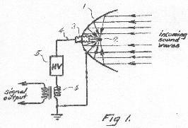
Fig. 2 illustrates a similar circuit to that shown in Fig. 1 except that probe 3 is
electrically-heated, heating current being provided by step-down transformer 9 from an AC
voltage source. The balance of the circuit is similar to that set forth in Fig. 1. The secondary
of step-down transformer 9 must be insulated from the primary to the limit of the high potential
supplied to probe 8.
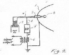
Fig. 2a is a detail of probe 8 provided with internal resistance heating. In this figure, probe
8 is spherical to provide optimum conditions for sound-pressure convergence. Resistance-heating
element 10 is contained within spherical container 6 and conducts heat thereto.
For convenience and safety in handling, insulated leads 4 and 4' (now 2-conductor) are contained
within flexible shielded cable 11 which also provides a ground to reflector 1, thereby
eliminating the need for an insulating bushing and a separate ground to
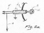
Fig. 2b is an alternate form of probe consisting of an exposed platinum or tungsten filament
12, heated (only) to a dull red (non-oxidizing) temperature.
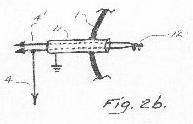
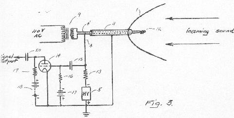
Fig. 3 is a more complete diagram showing reflecting surface 1, heated-filament probe 12, high
potential insulated leads 4 and 4' with flexible shield 11. Step-down transformer 9 supplies
current to heat probe 12. Capacitor 15 couples the changing voltage of lead 4 to the grid of
triode 14. The circuit which is illustrated is a conventional amplifying consisting of grid
bias resistor 16, bias supply 17, plate supply 18, plate resistor 19 and output coupling
capacitor 20.
It must be pointed out that power supply 5 must produce an output which is thoroughly filtered,
i.e. with minimum ripple. The voltage output should be sufficient to maintain intense ionization
and coronal emission around electrode-probe 2. For this purpose 10-15 KV has been found to be
satisfactory if probe 2 is of small dimensions,
When probe 2 is cold or not coated with specific materials to improve emission, polarity is
not important. Either positive or negative corona is effective. If probe 2 is heated,
the negative polarity is preferred. Various coatings may be applied to probe 2 so as to improve
either positive or negative emission.
It is obvious that there may be many variations in the shape or the sound reflecting surface
or in the electrodes and circuit making up the system without departing from the spirit of the
invention as set forth in following claims.
I Claim:
1) Method of converting sound waves into electrical signals consisting in directing said waves
into a focal spot by means of a reflecting surface, fixing an insulated electrode at said spot,
electrically charging said electrode to a high direct current potential relative to said
reflecting surface, and utilizing the resulting variations in the charging current to produce
electrical signals.
2) A microphone consisting of a parabolic reflector, an electrode positioned at the focus of
said reflector, means for charging said electrode relative to said reflector and means for
utilizing the variations in charging current as an output signal.
3) Apparatus for converting sound into electrical signals, consisting of an arcuate
sound-concentrating surface, an electrically-conducting probe at the focus of said surface,
means for providing a charging current of high potential to said probe and means for sensing the
variations in said charging current.
4) Apparatus according to Claim 3 including means for electrically heating said probe to
increase the emissivity thereof.
5) Apparatus according to Claim 3, including the coating of said probe with materials to
increase the emissivity thereof.
6) Apparatus according to Claim 3. including a probe composed of radioactive material to
increase the emissivity thereof.
Thomas Townsend Brown
San Francisco, California
June 12, 1967
Additional Claims:
Add:
7) Method of converting sound waves into electrical signals consisting in concentrating sound
pressure variations upon the coronal envelope of a high potential electrode, maintaining said
electrode at high potential and utilizing the resulting variations in the charging current to
produce electrical signals.
8) A microphone comprising a corona-emitting electrode charged to high potential, means to
concentrate incoming sound pressure upon the coronal envelope of said electrode and means to
utilize the resulting variations of corona current to produce output signals.
9) Electrokinetic apparatus for converting sound into electrical signals comprising an
electrode maintained at high potential so as to produce corona, means to concentrate sound upon
said corona and means to utilize the variations in corona current to produce output signals.
10) Apparatus according to Claim 9 including a horn to collect sound pressure and concentrate
the same upon said corona.
11) Apparatus according to Claim 9 including means for electrically heating said electrode to
increase the corona therefrom.
12) Apparatus according to Claim 9 including the coating of said electrode with materials to
increase the corona therefrom.
13) Apparatus according to Claim 9 including an electrode composed of radioactive material to
increase the corona therefrom.


Please be advised that this document is copyrighted © by The Townsend Brown family. All rights reserved.
Please see Legal and Copyright Information for additional copyright information.
