(Return to Index Page) By Robert Seaman
Capt. USAF Main Document | Supplement A | Supplement B Copyrighted © by The Townsend Brown family. All rights reserved.
1019 Dupont Circle Bldg.
Washington 6, D.C. Dear Sirs, Thank you for the material you sent two weeks ago, and for the pleasant visit I had with you. Electrohydrodynamics and the Tri-arcuate Ballistic Electrode have proven to be a very interesting and absorbing subject for my thesis. Enclosed is a copy of a report of my studies so far, that might interest you. The purpose of the report is to stimulate interest in the project, and to set down my thoughts. It is very sketchy, but perhaps something to base future studies on. I would appreciate any further information you care to send me concerning this work. Sincerely, /S/ Robert Seaman
Capt. USAF
Tri-arcuate Ballistic ElectrodeIII. Equations
Figure 1
Related Information
Velocity and ThrustIV. Experimental Data
Sample Calculations
Voltage DependencyV. Need for Data VI. Summary Bibliography
Pressure Dependency
Figure 2
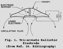 Fig.1. Tri-arcuate Ballistic Electrode - (from Ref. 16, Bibliography)
1. Elastic collisions between particles 2. No forces by ions on neutral molecules 3. The mass of the ions is the same as that of the surrounding medium 4. Homogeneous distribution of ions 5. The energy gained by an ion accelerated over a mean free path is less than the thermal energy of the surrounding moleculesThe force on a charged particle in an electric field is give by:
F = force (newtons) q = charge (coulombs) E = electric field strength (volts per meter)Therefore, the work done by the field on the particle must equal the kinetic energy gained, or:
d = distance through which ion is accelerated (meters) m = mass of ion (kilograms) Vd = drift velocity (meters / second)Where equation (2) is solved for drift velocity,
Vd = (2qEd / m)1/2 (3)
When d is assumed to be the mean free path, L (meters), of a molecule in a gas with thermal energy 1/2 mc2 (c = thermal velocity), then equation (3) can be written (Ref. 2:35)Vd = qE / mc (4)
This is the velocity of the ion wind under the listed assumptions. When the energy gained by the ions is greater than the thermal energy of the medium, equation (3) becomes (Ref. 8:70)Vd = (1.147qEd / m)1/2 (5)
where d is now a function of (E / p)1/2 where p is the gas pressure. It is clear that equation (3) is a good approximation. The momentum thrust of this device is given by the traditional rocket equation,T = m'Ve (6)
where,T = thrust (newtons) m' = mass rate of flow (kilograms / second) Ve = exhaust velocity (meters / second)
E = 107volt / m (Re. 9:116) L / c = 10-9 sec. (Ref. 8:41) q = e- = 10-19 coul. (Ref. 15:71) m = 10-26 kg. (Ref. 4)Equation (4) then becomes:
Vd = qEL / mc = (10-19 coul.)(107 volt)(10-9 sec.) / 10-26 kg m Vd = 105 m / secBy momentum exchange the ions drive the air with a wind velocity given by the equation for conservation of momentum:
Pa = density of air Va = wind velocity of the air Pi = density of ions.Assuming the concentration of ions is 1013 ions / cm3 in air with 1019 particles / cm3, and assuming their masses are equal, equation (7) yields:
Va = (Pi / Pa) Vd = (1013 / 1019) 105 m / sec = 0.1 m / sec
This value is similar to wind velocities of one foot per second, as found in the references (Ref. 15:72, and 11:chap 13, p 39). The current density would be given by:j = (1013 ions / cm3) (10 cm / sec) (10-19 coul / ion) = .01 ma / cm2
The thrust is given by equation (6), if it is assumed the exhaust velocity is equal to the wind velocity calculated above. This also assumes the velocity is directed opposite to the direction of motion. The density of atmospheric air is:.00238 slug / ft3, so that equation (6) yields:
T = m'aVe = (.00238 slug / ft3) (1 ft2 / sec2) T = .00238 lb / ft2The results of these calculations agree with those values observed by Whitehall-Rand, Inc. It should be emphasized that many factors have been ignored. Some of these are:
1. Temperature changes
2. The clustering effect of dust particles
3. Non-uniform field
4. Inhomogeniety
Voltage Dependency
It was experimentally determined that the thrust was proportional to the voltage squared. This characteristic is probably a consequence of space charge limitation (Ref. 15:68). Rewriting equation (6) by substituting:T = (i / q) Vd (11)
In the case of space charge limitation, the current density j is given by the Langmuir-Child Law as:j = k1 E3/2 / d1/2 (12)
where k1 = a constant. Substituting the value for j from equation (12), and Vd from equation (3), equation (11) becomes:Pressure Dependency
The following were drawn from data obtained by Whitehall-Rand, Inc.: The upper curve shows the thrust constant with pressure, and the lower curve shows the decrease in current i with pressure. These data were taken at constant voltage. The break in the curves in the neighborhood of 10-3 mm Hg is the result of the gas breakdown. (Ref. 9) Sparking was observed, with the resulting increase of current, and power source cut off. As the pressure was further decreased, breakdown voltage increased again, as predicted by theory, until no sparking was observed. At this point measurements were resumed. The thrust curve is seen to be a straight line of constant value. This is predicted by equation (13) under the space charge limitation. And, the current curve decreases with pressure as predicted by equation (12) since d, the distance between collisions, increases as the pressure decreases. Other characteristics reported by Whitehall-Rand are explainable by the above theory.1. Examination and plotting of the electric field around and in the device, 2. Measurements of the ion flow and velocity and the air flow and velocity, 3. Measurement of the charge and mass of the ions, 4. Further measurement of the pressure and voltage relationships at low pressures, 5. Determination of optimum size and shape relations related to drag, 6. Determination of the constants in the space charge limited current and thrust equations, 7. Application to the space environment, and limitations of the theory.
T = (k2 / m) E2 (13)
Verification of this theory is necessary, and further data is needed on the characteristics of this device.Bibliography
1. Alfven, Hannes. Cosmical Electrodynamics. Oxford:; Clarendon Press, 1950. 2. Cobine, J.D. Gaseous Conductors. New York: McGraw-Hill Book Co, Inc., 1949. 3. Deutsch, W. "Is the Action of Electrical Gas Purification Due to 'Electrical Wind'?" Annals der Physik (Fifth Series), 9:249-264, (1931). 4. Hausmann, Erich, and E.P. Slack. Physics (Third Edition). New York: D. Van Nostrand Co., Inc., 1948. 5. Jeans, Sir James. The Mathematical Theory of Electricity and Magnetism (Fifth Edition). Cambridge: Cambridge University Press, 1946. 6. Lapple, C.E. "Dust and Mist Collection," in Chemical Engineering Handbook (Third Edition), edited by J.H. Perry. New York: McGraw-Hill Book CO, Inc., 1950, p. 1039. 7. Llewllyn-Jones, Frank. Ionization and Breakdown in Gases. New York: John Wiley and Sons, Inc., 1957. 8. Loeb, L.B. Basic Processes of Gaseous Electronics. Berkeley: University of California Press, 1955. 9. --------. The Mechanism of the Electric Spark. Stanford University: Stanford University Press, 1941. 10. --------. "Recent Developments in Analysis of Positive and Negative Coronas in Air," Journal of Applied Physics, 19:882-896, (October, 1948). 11. Magill, P.L. et al ed. Air Pollution Handbook. New York: McGraw-Hill Book CO, Inc., 1956. 12. Perel', V.I. "Calculations of the Drift Velocity of Ions in the Electric Field in Their Gas." Soviet Physics JETP, 5, No. 3:440-444, (October, 1957). 13. Thomson, J.J. and G.P. Thomson. Conduction of Electricity Through Gases (Third Edition). England: Cambridge University Press, 1928, Vol. I and II. 14. White, H.J. "Particle Charging in Electrostatic Precipitation." Transactions of American Institute of Electrical Engineers, 70(Pt II):1186-1191, (1951) 15. --------. "Role of Corona Discharge in Electrical Precipitation Processes." Electrcial Engineering, 71:67-73, (1951). 16. Whitehall-Rand, Inc. Patent Application for Tri-arcuate Ballistic Electrode. 1959.