"Flow Control System"
(Return to Index Page)
Docket No. 8308
Thomas Townsend Brown
1236 Chestnut Street
San Francisco, California 94109
Copyrighted © by The Townsend Brown family. All rights reserved.


Reference:
A) U.S. Patent No. 2,949,550 - "Electrokinetic Apparatus"
B) U.S. Patent No- 3,018,394 - "Electrokinetic Transducer"
1) In (A), a two-element (2 electrode) structure is shown whereby electrical energy is converted
directly into fluid flow without the aid of moving parts. The device has immediate commercial
application as a noiseless fan.
2) In (B) the same basic two-electrode structure shown in (A) is electrically modulated to
serve as an electro-sonic transducer. An alternating current (signal) is superimposed upon
the direct current bias to produce pulses of air or sound waves. The device operates either
as a loudspeaker or the converse, as a microphone. The disadvantage of the system is that
especially with a large loudspeaker, the entire supply current must be modulated by the signal.
This requires an excessive amount of signal energy and expensive amplifiers.
3) In the present application, a third element is included as a "control grid" in much the
same manner (and for the same reason) as the grid of a triode. In this case however, the grid
controls the shape of the electric field and hence the emission of ions from the fine-wire
anode in the direction of the plate* (cathode). The transfer of momentum from ions to the host
medium (air) and the electrostrictive gasdynamic effect upon the fluid dielectric cause the
dielectric fluid (air) to move in the direction of the divergence of the electric field. The
polarity is not specific. The polarity may be reversed without changing the direction of the
air flow. The volume of flow with reversed polarity is approximately the same, but reversed.
polarity results in undesirable side effects. When the fine wire is negative, a "beaded" type
of corona (quite different from the smoothly-luminous positive corona) surrounds the wire.
The "beads" are regions of excessively high (local) field gradients and produce large
quantities of ozone and a hissing sound. Positive corona, therefore, is preferred.
4) In general, the invention represented in the present flow control system, reminds one of
the advantage gained, in the history of the vacuum tube, by the addition of the control grid
(DeForest et al) to the earlier diode rectifiers (Edison effect). The grid placed between the
filament and plate controlled the flow of electrons from the cathode to the anode. This
resulted in the concept of the electronic "valve" and, hence, the power amplifier by which
relatively large plate current could be controlled by almost insignificant grid current. The
application of the control grid to the vacuum tube diode was a major breakthrough in early
radio technology.
The situation in much the same in the present invention except that the flow is now composed
of air ions or fluid ions, usually (though not necessarily) at atmospheric pressure. In the
present instance, the grid controls the flow of the fluid, gaseous or liquid, through the
electrode assembly. But it also operates as an amplifier, either to control the relatively
large energy of fluid flow or to control current in the "plate circuit" similar to a 3-element
vacuum tube.
Undoubtedly there may be special applications where controlled flow of a fluid medium is not
necessarily the objective and a current amplifying device, based on the above affect, may be
more useful. If so, there should be claims directed toward this possibility.
The flow-control described herein would appear to have its principal field of usefulness as an
electro-acoustic transducer or loudspeaker. The electro-acoustical efficiency, because of the
amplifying action appears to be at least one order of magnitude higher than that of conventional
electromagnetic or electrostatic loudspeakers, which have no amplifying capability. This
increase in efficiency is intrinsic in the control grid. The small signal current applied to
the grid produces relatively large acoustic output, with the additional energy being supplied
by the relatively inexpensive DC bias. The device operates concurrently as an amplifier and
transducer. It is important to repeat that this is not the case with any other type of
loudspeaker on the market today.
Suggested Specifications:
1) This invention relates to fluid flow-control devices whereby a varying electric input is
made to control or regulate output pressure or flow of an ionizable dielectric fluid.
2) This invention relates to alectro-scoustic transducers, loud speakers or the like, whereby
an electric signal produces sound without the aid of a diaphragm or other moving part.
3) This invention relates to amplifying devices whereby relatively small input energy controls
and generates a relatively large output energy.
1) This invention features a fluid control system, which has no moving mechanical parts, the
response of which is practically instantaneous.
2) This invention features a system, which is noiseless in operation.
3) This invention features a loudspeaker which operates with unusually high signal efficiency
by reason of the feet that it is an electro-acoustic amplifier. This loudspeaker has no
diaphragm or other moving element and has virtually no inertial or Doppler distortion.
4) This Invention features a loudspeaker which has a full-range frequency response (believed to
extend from a few cycles per second to beyond 250 KC per second in air at atmospheric pressure)
free from resonance peaks or mechanical distortion.
Referring to the attached drawings:
Fig. 1 is a diagram of an electrical circuit with associated electrodes by which a flow of a
medium is controlled.
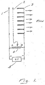
Fig. 2 is a diagram of a circuit with associated electrodes by which flow pulses or sound waves
are produced.
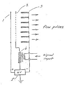
Fig. 3 is a diagram, partly in perspective, showing the physical structure of electrodes set
forth in Fig. 1.
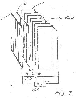
Fig. 4 is an electrical circuit producing results similar to that in Fig. 2 but using a vacuum
tube for producing the modulated signal rather than a transformer.
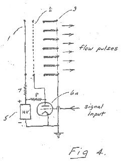
Fig. 5 is a perspective diagram similar to Fig- 3 showing a two-sided electrode structure to
produce a "push-pull" action for the generation of sound waves.
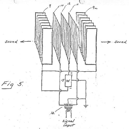
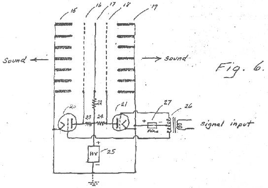
Fig. 6 is a circuit diagram showing the application of vacuum tubes for "push-pull" operation
an in Fig. 5.
 Referring in more detail to the attached drawings
:
Fig. 1 illustrates the simplest form of the invention, and sets forth the circuit by which the
control principle is applied to the flow of a dielectric fluid. The diagram illustrates
basically three electrodes. Filaform electrode 1 consists of a fine-wire or grid of fine wires.
These wires are usually less than .003" in diameter and may be formed of any conducting
material., stainless steel., tungsten or the like which is both mechanically strong and
resistant to corrosion. In practice, stainless steel wires approximately .0015" to .0025"
diameter have been found to be satisfactory.
High voltage is provided by power supply 5. In most applications the requirements call for
7,500 to 25,000 volts with current demands proportional to the size of the system. Current
requirements usually range from 1 milliampere up to several hundred milliamperes for the
larger installations. A convenient form of power supply includes a 60 cycle step-up transformer
and a voltage-tripler rectifier circuit with ripple less than 1%. Depending upon the system
requirements, either the positive or negative output side of the power supply may be grounded,
or the entire power supply may be floating with respect to the ground. The ground connection in
no way affects the rate of flow or controllability of the flow.
When energized, electrode 1 is surrounded by a coronal envelope which is smooth, silent and
slightly luminous. The air in the region of the envelope is intensely ionized, generating both
positive and negative ions. The negative ions are pulled into the positive electrode and
discharged. The positive ions are repelled by the fine-wire electrode and travel outward in
the general direction of electrode(s) 3. The arrangement and spacing of these electrodes is
such as to provide a divergent electric field from electrodes 1 outward toward electrodes 3.
Positive ions falling through this electric field tend to accelerate in the direction of 1 to
3 and transfer their momentum to the host media (air) in doing so. Air is then driven through
the electrode structure by "ion momentum transfer".
Concurrently, electrostrictive gasdynamic forces are created in the divergent electric field
which tends to drive the entire volume of dielectric fluid in the space between the electrodes
in the direction of the divergence of the electrostatic field. Gasdynamic pressure is initiated
in the coronal envelope (so-called corona pressure) and this extends outward in the direction
of the divergent electrostatic field, i.e...towards electrode(s) 3. This pressure is constant
when the field is constant.
If, however, the field varies this pressure varies instantly. Control electrode 2, placed in
the divergent field is capable of altering the field according to the charge it carries. Hence,
a variation in the potential of electrode 2 causes a change in the shape of the steady
electrostatic field created between electrodes 1 and 3A as to affect the electrode pressure
and the augmentation of corona pressure produced by electrostriction. The sudden change in
pressure produces sound waves.
Electrostrictive gasdynamic pressure augments the flow produced by ion momentum transfer. Both
of the above pressure components, tending to cause flow of the dielectric medium are governed
by the shape and intensity of the electrostatic field between electrodes 1 and 3.
Electrostrictive gasdynamic pressure is virtually instantaneous with the applied electric field
whereas pressure resulting from ion-momentum transfer is relatively slow in building up. (This
is because of the "time-of-flight" of the slow-moving positive ions).
Electrode 2, in the form of a wire grid or screen, is placed in the electrostatic field between
electrodes 1 and 3. A variation in the electrical potential of electrode 2 readily affects the
shape and intensity of this field and, hence affects the resultant flow of dielectric medium
through the field.
In Fig. 1, for purposes of describing the basic aspects of the invention the electrical
potential applied to electrode 2 is varied by rheostat 4. When the slider of the rheostat is
in position "A" the potential of control grid 2 is the same as that of electrode 1. This
virtually eliminates the field around electrode 1, extinguishes the corona around electrode
1, stops the generation of ions and minimizes the resulting flow of dielectric fluid.
When the slider of rheostat 4 is in position "B", the electrostatic field around electrode 1
is increased and the coronal envelope and ion emission is intensified. This results in
increased flow of dielectric fluid through the system of electrodes so that when rheostat 4
is in position "B" this flow is maximum. The rate of flow can be varied or modulated by
changing the potential of electrode 2 by shifting the rheostat between position "A" and "B".
Fig. 2 illustrates a basic structure similar to that of Fig. 1 except that the potential of
control grid 2 is shifted rapidly (modulated) by transformer 6 from a signal input.
Fig. 2 shows high voltage power supply 5 with mid-point connected to one side of transformer 6,
which mid-point may also be grounded if such grounding is desirable. Rapid fluctuations in the
potential applied to control grid 2 cause virtually instantaneous flow pulses to be emitted by
the system (as shown by the arrows). This results mainly from electrodtrictive gasdynamic pulses
rather than ion-momentum transfer. When the potential of the control grid is constant the
resulting flow of dielectric media is constant.
Fig. 3 is a diagram similar to Fig. 1 with electrodes 1. 2 and 3 shown in perspective. Electrode
1 is a grid of fine wires, control electrode 2 is a grid or screen of coarse wires (with wire
diameter exceeding .025"). Electrode(s) 3 is an edgewise array of plates made of conducting or
partially-conducting material. Metallic plates are satisfactory in most cases, although a
screen may be used in place of the edgewise array of plates, but screen is found to be less
satisfactory.
Where very high voltages are used or when inter-electrode spacing is small, it is found
desirable in some cases to use plates of poorly conducting material. The reason for this
is to prevent damaging electrical break-down across the air gap between the electrodes. When
plates 3 are fabricated of a material (such as a plastic loaded with carbon powder) so as to
have a resistivity in the range from 10
6 to 10
10 ohms per cubic
centimeter, the possibility of damaging spark breakdown to the edge of the plates is virtually
eliminated. The low conductivity prevents the localization of an intense electric field which
must precede spark breakdown.
It is also helpful to provide the leading edges (edges nearest the anodes) of electrodes 3
with a substantial radius so as to eliminate sharp edges facing the highly-charged grid. It
is found that well rounded edges improve not only the flow but the quality of the sound
produced by the device when operating an a loudspeaker. Troublesome hissing is almost completely
eliminated by rounding all cathodic edges.
In an electrode system where it is of primary importance, as in the present invention, to
create a divergent electrostatic field and where the operating efficiency depends primarily
on the degree of divergence, the electrode shape and field geometry are important if not
critical. The fine-wire electrodes must have minimum surface area and the plate electrodes
must have a surface area several orders of magnitude larger. The operability depends upon
area differential. The effectiveness also depends on the emissivity of the electrodes, i.e.,
the anodes for the emission of positive ions and the cathodes for the emission of electrons
and the establishment of a negative space charge. Toward that end, it is desirable to coat
the electrodes with materials to increase their emissivity.
In certain special cases, operation is improved by heating the electrodes to provide thermal
ionization and the emission of thermions. Toward this end, the fine-wire anode may be heated
by including the same in a resistance-heating electrical circuit. Since this is an obvious
arrangement it is not shown specifically in the drawings. Coating the electrodes with such
materials, as cesium or barium. chloride, thorium oxide or certain radioactive materials may
be resorted to whenever indicated.
Fig.4 is a diagram of an acoustic pulse-forming system similar to that shown in Fig. 2 but
using a vacuum tube (6A) instead of a transformer for energizing the control grid 2 from a
signal input. Resistor 7 is a current-limiting protective device to prevent a breakdown in
the air space between electrodes 1 and 2 during excessive voltage peaks. Resistor 8 conducts
plate current to triode (6A), permitting the control grid 2 to engage in voltage swings from
that represented by the limit of the power supply 5 to almost ground potential, depending upon
the signal applied to the grid of the triode.
In short, the energy of the input signal is amplified once in the triode and again in the
flow-control system. A relatively small input signal results in the generation of heavy flow
pulses or sound waves.
Fig. 5 is a diagram, along with a perspective view of the screens and plates of a sound
generating system for "push-pull" operation. Due to the fact that the electrode structure is
electrically balanced there is no net flow of air an in structures previously illustrated.
Sound waves are produced by the electrical action upon the air column between the electrodes,
first in one direction and then in the other. It is to be noted that electrodes 9 and 9A are
connected together to the negative side of the power supply 13. The positive side of the power
supply 13 connected to the fine-wire grid 12. Coarse-wire grids 10 and 11 are connected to
opposite ends of the secondary of transformer 14, the midpoint of which connects to that of the
power supply 13 and to the ground (if a ground is desirable). Signal input to the primary of
transformer 14 is stopped up to produce relatively high opposing potentials between control
grids 10 and 11 so that pressures are directed first one way then the other, (left or right as
indicated) causing a push-pull generation of sound waves in the air column.
Fig. 6 is a diagram including vacuum tubes to produce essentially the result as that shown in
Fig- 5 but free from the distortion introduced by a high voltage transformer (with its frequency
limitations caused by its inter-winding capacitance, etc.). The system set forth in Fig. 6 is
desirable because of its high fidelity capability.
Electrodes 15 and 19 are connected to the negative side of the high voltage power supply 25 and
can be grounded if convenient. From a practical standpoint, it is desirable to use electrodes
15 and 19 as protective grids at, the sides of the commercial type loudspeakers and to
electrically ground these protective grids. The fine-wire anode 17 is conveniently protected
against damage in the center of the structure and is maintained at a high DC positive potential
from power supply 25.
Resistor 22 serves as a current-limiting device to prevent damage due to accidental wire
breakage or electrical breakdown within or near electrode 17.
Resistors 23 and 24 convey the plate potential to triodes 20 and 21 and, at the same time,
permit the plates to engage in voltage swings which are conducted to control grids 16 and 18
respectively. Signal input is applied to the primary modification transformer 26 feeding
"push-pull" to the grids of the two triodes. A suitable bias supply 27 is shown in connection.
In this form of the invention, as an electro-acoustic transducer, as shown also in Fig. 4, there
are in reality, two stages of amplification resulting from the use of 1) a vacuum tube triode,
and 2) a control grid in the transducer itself. Because of such double amplification, the purity
of signal-input (in, a range less than 1 volt can be maintained. This is especially desirable
in super high-fidelity systems.
It is to be understood in the interpretation of the foregoing drawings that control devices or
loudspeakers operating in accordance with the principles described herein are in no way limited
in size. The smallest units my be suitable for portable loudspeakers. The largest units, built
by assembling modules to sizes measuring several hundred square feet in radiating area, are for
theatre or auditorium use.
There may be many variations in the fan of the control electrode or the circuit by which it is
linked into the system without departing from the spirit of the invention as set forth in the
following claims:
Suggested Claims:
1) Method for producing and controlling flow of a dielectric medium consisting in establishing
a non-linear electrical field between a system of three or more electrodes immersed in said
medium, utilizing one of said electrodes as a control grid and applying electrical potential to
said, control grid for the purpose of increasing or reducing said flow.
2) Method for generating pressure pulses in a dielectric fluid in accordance with an electrical
signal consisting in utilizing at least three electrodes immersed in said fluid,, charging two
of said electrodes to produce an electric field there between and utilizing a third electrode
as a control grid to which said electrical signal is conducted.
3) In a system of three or more electrodes which may be differently charged, said electrodes
being capable of producing a non-linear electric field there between, the use of at least one
electrode to serve as a control grid to vary the flow of a dielectric medium through and between
said system of electrodes.
4) A current amplifying device consisting of two or more electrodes immersed in an ionizable
dielectric fluid, means for supplying a DC charging current to said electrodes, a control grid
located in the field of said electrodes, means for supplying a varying current to said control
grid and means for utilizing the corresponding amplified variations in the charging current to
said electrodes.
5) In a system according to claim 3, the use of coatings applied to the electrodes thereof to
improve the emissivity of said electrodes.
6) In a system according to claim 3, the use of partially-conducting materials in the electrodes
thereof to prevent electrical breakdown between said electrodes.
7) In a system according to claim 3 the use of vacuum tubes in combination therewith to modulate
the electrical potential applied to the control grid.
8) Two system according to claim 3 combined in contra-acting arrangement to provide reversible
or push-pull forces on the fluid dielectric.


Please be advised that this document is copyrighted © by The Townsend Brown family. All rights reserved.
Please see Legal and Copyright Information for additional copyright information.
