"Electrokinetic Apparatus"
(Return to Index Page)
Published in Psychic Observer, Vol. XXXVII, No. 1
Excerpts from U.S. Patent Ser. No. 2,949,550. Filed July 3, 1957.


My invention of an electrokinetic apparatus is virtually
a method and apparatus for utilizing electrical potentials in the production
of forces for the purpose of causing relative motion between a structure
and the surrounding medium.
Priorly, intervening electrokinetic apparatus has
been employed to convert electrical energy to mechanical energy and then
to convert the mechanical energy to the required force. Except for the
insignificantly small forces of electrostatic attraction and repulsion,
electrical energy has not been used for the direct production of force
and motion.
Since any conversion of energy from one form to another
is accompanied by losses due to friction, radiation or conduction of heat,
hysteresis, and the like, as well as serious reductions in the availability
of the energy by increases in the entropy of the system, it is apparent
that great increases in efficiency may be achieved through the use of the
direct production of electrical energy and force and motion made possible
by my invention. Likewise, the elimination of the machinery for the
intermediate conversion results in great savings in first costs,
maintenance, weight and space, the latter of two being of great importance
in self-propelled vehicles including mobile vehicles such as aircraft and
spacecraft.
The specific reasons for designing this electrokinetic
device are to provide:
1) An apparatus for converting the energy of an electrical
potential directly into a mechanical force suitable for causing relative
motion between a structure and the surrounding medium.
2) A novel apparatus for converting an electrical
potential directly to usable kinetic energy.
3) A novel apparatus for converting electrostatic
energy directly into kinetic energy.
4) A vehicle motivated by electrostatic energy without
the use of moving parts.
5) A self-propelled vehicle without moving parts.
6) An apparatus for producing relative motion between
a structure and the surrounding medium which apparatus includes a pair
of electrodes of appropriate form held in fixed spaced relation to each
other and immersed in a dielectric medium and oppositely charged.
7) Apparatus which includes a body defining one electrode,
another separate electrode supported in fixed spaced relation by said body,
and a source of high electrical potential connected between the body and
the separate electrode.
8) Apparatus having a body which is hollow and a source
of potential contained within the body.
9) Apparatus having a body and an electrode connected
to the body, which combination comprises a vehicle.
10) Apparatus which comprises a plurality of assemblies,
each including a body and an electrode secured in side-by-side spaced
relation to each other.
11) Vehicular apparatus which includes a pair of electrically
conductive body portions joined by an insulating portion, whereby said
electrically conductive portions constitute the electrodes.

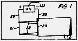
Referring to the drawings, I have illustrated in Figure
1 a simple form of apparatus which is readily adaptable for use in
demonstrating the principles of my invention, and which is utilized in this
application as a simplified representation to facilitate an understanding of
the principles involved. The apparatus illustrated in Figure 1 constitutes
one electrode which is preferably in the form of a body member 20, said
member preferably comprising a relatively thin flat plate. A second
electrode 21 in the form of a wire or other suitable form of electrical
conductor is held as by means of insulated supports 22 in fixed spaced
relation to the body 20, the wire 21 being disposed in the plane of the
body 20 and preferably substantially parallel with a leading edge 23 of the
body 20. A source 24 of high voltage electrical potential is provided and
connected as shown at 25 and 26 to the two electrodes 20 and 21
respectively.
I have discovered that when apparatus of the character
just described is immersed in a dielectric medium, as for example, the
ordinary air of the atmosphere, there is produced a force tending to move
the entire assembly through the medium, and this force is applied in such
direction as to tend to move the body 20 toward the leading electrode 21.
This force produces relative motion between the apparatus and the
surrounding fluid dielectric. Thus, if the apparatus is held in a fixed
position, the dielectric medium is caused to move past the apparatus and to
this extent the apparatus may be considered as analogous to a pump or fan.
Conversely, if the apparatus is free to move, the relative motion between
the medium and the apparatus results in a forward motion of the apparatus,
and it is thus seen that the apparatus is a self-propulsive device.
While the phenomenon just described has been observed and its
existence confirmed by repeated experiment, the principles involved are not
completely understood. It has been determined that the greatest forces are
developed when the leading electrode is made positive with respect to the
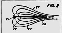
body 20, and it is accordingly thought that the immediate vicinity of the
electrode 21 where the potential gradient is very high, free electrons are
stripped off of the atoms and molecules of the surrounding medium. These
electrons migrate to the positive electrode 21 where they are collected.
This removal of free electrons leaves the respective atoms and molecules
positively charged and such charged atoms and molecules are accordingly
repelled from the positive electrode 21 and attracted towards the negative
electrode 20. The paths of movement of these positively charged particles
appear to be of the nature represented by the lines 27 in Figure 2.
It appears that upon reaching or closely approaching the
surface of the body 20, the positively charged atoms and molecules have
their positive charges neutralized by the capture of electrons from the
body 20 and in many cases, it may be that excess electrons are captured
whereby to give such atoms and molecules a negative charge so that they are
actually repelled from the body.
It will be appreciated that the mass of each of the
individual electrons is approximately one two-thousandths the mass of the
hydrogen atom and is accordingly negligible as compared with the mass of the
atoms and molecules of the medium from which they are taken. The principle
forces involved therefore are the forces involved in moving the charged
atoms and molecules from the region of the positive electrode 21 to and
beyond the negatively charged body 20. The force so exerted by the system
on those atoms and molecules not only produces a flow of the medium relative
to the apparatus, but, of course, results in a like force on the system
tending to move the entire system in the opposite direction; that is, to
the left as viewed in Figure 1 of the drawing.
The above suggested explanation of the mode of operation of
the device is supported by observation of the fact that the dimensions and
potentials utilized must be adjusted to produce the required electric field
and the resulting propulsive force. Actually I have found that the potential
gradient must be below that value required to produce a visible corona since
corona is objectionable inasmuch as it represents losses through the
radiation of heat, light and molecular charges in the medium.
My experiments have indicated that the electrode 21 may be of
small diameter for the lower voltage ranges, i.e. below 125 kv. while above
this voltage, rod or hollow pipe electrodes are preferred. These large
electrodes are preferred for the higher voltages since sharp points or edges
are eliminated which at these elevated potentials would produce losses thus
diminishing the thrust. For example, electrodes to be operated at potentials
below 125 kv. may be made from small gauge wire only large enough to provide
the required mechanical rigidity while electrodes to be operated at
potentials above 125 kv. may be hollow pipes or rods having a diameter of
1/4 to 1/2 inch.
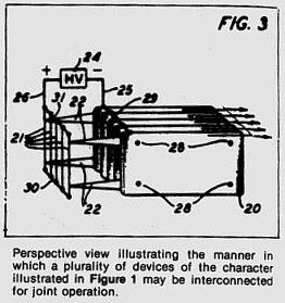
In Figure 3, I have illustrated the manner in which a
plurality of assemblies, such as are shown in Figure 1, may be
interconnected for joint operation. As may be seen from Figure 3, a
plurality of such assemblies are placed in spaced side-by-side relation.
They may be held fixed in such spaced relation through the use of a
plurality of tie rods 28 and interposed spacers (not shown) placed between
adjacent plates 20. The assembly of plates 20 may be electrically
interconnected by a bus bar or similar conductor 29 to which the negative
lead 25 is connected. in a similar way, the plurality of positive leading
electrodes 21 may be held in appropriately spaced relation to each other by
fastening their ends to pairs of bus bars 30 and 31, to the latter of which
the positive lead 26 is connected. The assembly of leading electrodes 21 may
be held in spaced relation to the assembly of the body members 20 by an
appropriate arrangement of the supports 22.
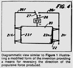
In Figure 4, I have illustrated diagrammatically an
arrangement of parts for producing a reversible action; that is, permitting
the direction of the propulsive force to be reversed. The apparatus is
similar to that shown in Figure 1, differing therefrom in utilizing a pair
of leading electrodes 21f and 21r spaced by means of spacers 22 from the
front and rear edges 23f and 23r of the body member 20 in a manner similar
to that described with reference to the supports 22 in Figure 1. The source
24 of high voltage electrical potential has its negative terminal connected
to the body 20 as by means of the aforementioned conductor 25. the positive
terminal is connected as by means of the conductor 26 to the blade 27 of a
single-pole, double-throw switch, serving in one position to connect the
conductor 26 to a conductor 26f which is in turn connected to the forward
electrode 21f and arranged in its opposite position to connect the conductor
26 to a conductor 26r which is in turn connected to the reverse electrode
21r.
It will be seen that with the switch 27 in the position shown
in Figure 4, the apparatus will operate in the manner described in
connection with Figure 1, causing the assembly to move to the left as
viewed in Figure 4. By throwing the switch 27 to the opposite position, the
direction of the forces produced are reversed and the device moves to the
right as viewed in Figure 4.
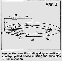
In Figure 5, I have illustrated the principles of the
invention as embodied in a simple form of mobile vehicle. This device
includes a body member 50 which is preferably of the form of a circular
disc somewhat thicker in its center than at its edges. The disc 50
constitutes one of the electrodes and is equivalent of the body member 20
referred to in connection with Figure 1. A leading electrode 51 in the form
of a wire or similar small diameter conductor is supported from the body 50
by a plurality of insulating supports 52 in uniform spaced parallel relation
to a leading edge portion 53 of the body 50. A skirt or similar fairing 54
may be carried by the body 50 to round out the entire structure so as to
provide a device which is substantially circular in plan. A source of high
voltage electrical potential 55 is provided with its negative terminal
connected as indicated at 56 to the body 50 and its positive terminal
connected as indicated at 57 to the leading electrode 51.
The device operates in the same manner as the apparatus shown
in Figure 1 to produce a force tending to move the entire assembly through
the surrounding medium to the left as viewed in Figure 5 of the drawing.
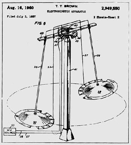
Referring now to Figure 6, there is depicted an illustrative
embodiment of this invention in which a pair of mobile vehicles, such as
depicted in Figure 5, are shown suspended from the terminals of arm 40,
which arm is supported at its midpoint by a vertical column 41. High voltage
source 55 is shown connected through wires 56 and 57 which extend to the
ends of arm 40 by way of suitable rotatable contacts 44 and 45 and brushes
46 and 47 adjacent point 43 in the center of arm 40. Mobile vehicle 50 is
shown suspended from on end of the lever arm 40 by means of conductors 56
and 57. A similar vehicle 58 is shown suspended from the other end of the
rotatable arm of conductors 56 and 57. It is, of course, understood that
these bodies may be suspended by any convenient structure such as wires or
rods which wires or rods may support conductors 56 and 57 in any suitable
manner.
In this illustrative embodiment the vehicles were caused to
rotate at a speed of 17 feet per second with 50 kv. applied to the
conductors 56 and 57 from source 55. it is, of course, understood that
these figures are merely by way of illustrative example and, as might be
expected, the speed of the vehicles increases exponentially with the applied
voltage.

When the apparatus is to be used for propelling a mobile
vehicle, it is, of course, necessary that the source 55 of high voltage be
contained within and carried by the vehicle. This may be accomplished by
using the apparatus in the manner shown in Figure 7, wherein the high
voltage source 55 is contained within the hollow central portion of the body
50, the conductor 56 being connected to the body and the conductor 57 being
suitably insulated from the body 50 and extended externally thereof and into
connection with the leading conductor 51.
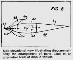
The apparatus of my invention may be used to propel vehicles
of shapes other than that described in connection with Figures 5 and 7. For
example, in Figure 8 I have illustrated the way in which the invention may
be utilized in the propulsion of a vehicle of torpedo-like shape. As shown
in Figure 8, I use a body member which is indicated generally be the
reference character 60 and which is formed three parts, to wit, an afterbody
61 formed of electrically conductive material, a hollow central body portion
62 formed of insulating material, and a nose portion 63 formed of
electrically conductive material. A source 64 of high voltage electrical
potential is contained within the hollow central body portion 62 and has
its terminals connected, respectively, to the nose portion 63 and afterbody
portion 61, the positive terminal being preferably the one which is
connected to the nose portion 63. Thus, the afterbody 61 functions as the
aft electrode 20 described wit reference to Figure 1 and the nose portion
63 corresponds to the leading electrode 21.
The nose portion 63 may be equipped with a plurality of
suitably shaped fins 65. These fins may be extended aft of the junction
between the central body 62 and the nose portion 63, as shown at 66, to
provide ionizing elements which are spaced more closely to the afterbody
61 and which functions in a manner analogous to the smaller diameter
electrode 21. Also, the fins may be shaped to conform to the aerodynamic
requirements and may, if desired, be movable in whole or in part for the
purpose of permitting the machine to be maneuvered.
I have shown the nose portion 63 as being provided with a
needle-like point 67. By using such a nose form, which at present appears
to be the best suited for flying speeds approaching or exceeding the speed
of sound, I am able to produce an ionization of the atmosphere in the
immediate region of this foremost portion of the mobile vehicle. I believe
that this ionization facilitates piercing the sonic barrier and minimizes
the abruptness with which the transition takes place in passing from
subsonic velocities to supersonic velocities.
From the foregoing it will be observed that I have provided an
electrokinetic method and apparatus for the production of forces suitable
for causing relative motion between a structure and the surrounding medium.
It will be observed that the methods and apparatus described herein are
particularly adaptable for use as a propulsive means for self-propelled
vehicles. I wish to emphasize that the high voltage power source referred
to herein may be of relatively simple construction and relatively simple
construction and relatively low capacity. For example, potentials of the
order of 30 to 70 thousand volts may be adequate for use with this
apparatus, the particular voltage employed dependent, of course, upon the
size of the vehicle or apparatus. It will be appreciated that the
elimination of moving parts in the apparatus will represent a tremendous
savings in first cost and maintenance cost of the apparatus. Also, the
direct production of the motive forces from the electrical force represents
a high efficiency so that greater propulsive speeds may be obtained with
apparatus occupying small space and of light weight.
