"Electrokinetic Apparatus"
(Return to Index Page)
Docket No. 8780
Thomas Townsend Brown
1001 3rd. Street
Santa Monica, Calif. 90403
Copyrighted © by The Townsend Brown family. All rights reserved.


Comments:
In all of the applicant's former patent disclosures for "producing relative movement between an
electrode structure and the ambient fluid medium," metal electrodes are specified either
directly or indirectly. In most cases, the electrodes have been referred to as "electrically
conducting." Sometimes these electrodes are coated with various materials such as cesium,
thorium oxide or the like, to improve emissivity. In one instance, (Patent 793,893 EHD Fluid
Pump) the smaller of the two "principal" electrodes is made electrically-resistive but this
resistivity is indicated only for the smaller of the two electrodes (the pointed emitter).
The first reference to electrically-resistive material for the larger electrode appears in
Patent Application 662,105, "Fluid Flow Control System", filed August 21, 1967.
Recent experiments covering the use of electrically-resistive materials for the large
electrodes (the array of vanes) has revealed surprising results. This change has made it
possible to obtain air velocities and sound densities several times that obtained from the use
of bare-metal electrodes. These improved results are obtained for two reasons:
In application 662,105, these advantages were known and the specification and claims included
the use of resistive materials in the fabrication of the larger electrodes, but that patent
application referred specifically to a three-electrode (triode) structure rather than a
two-electrode (diode) structure. It is the purpose of the present application to cover
specifically the use of electrically-resistive materials in the fabrication of the vanes in
the diode.
Earlier Patent Coverage:
In Bennett Patent No. 2,327,588 the use of an elongated (filiform) electrode is taught. This
disclosure (now in public domain) may tend to compromise certain of the applicant's coverage in
Patent 2,949,550 (currently assigned to Decker). If, upon careful investigation, this is found
to be the case, that part of the Decker-held patent may also be considered to be in the public
domain. The purpose of the present application, therefore, is to provide independent patent
coverage by specifying the electrically-resistive materials.
Objects of the Invention:
1. To provide relative movement between an electrode structure and the ambient fluid medium so
as:
2. To provide an electrode structure capable of creating an intense electrical field without the
possibility of electrical breakdown across the fluid gap.
3. To serve as an improved flow-control device comparatively free from the danger of
electrical breakdown.
4. To serve as an electrogasdynamic loudspeaker wherein extreme voltage peaks would not
cause sparking.
5. To provide an electrogasdynamic loudspeaker with improved acoustical volume and
frequency response.
6. To provide a fan or pump for combustible fluids which is relatively free from explosion
hazards.
7. To provide an electrogasdynamic fan having Increased velocity and improved electrical
efficiency.
8. To serve as an electrostatic precipitator whereby suspended matter in the fluid medium
is deposited upon and hold by the vanes with increased retentivity.
9. To provide an electrostatic precipitator with disposable vanes which are relatively
inexpensive.
10. To provide such electrokinetic devices with an electrode structure which is free from
electrical hazards and is not dangerous to touch.
Specifications:
the electrokinetic device described herein is believed to operate by virtue of two contributing
forces:
The above forces cause a flow of any ionizable dielectric fluid medium generally in the
direction from the fine wire toward the vanes and thru the region between the vanes. This flow
is a function of the voltage applied between the fine wire and the vanes. In the present
instance, where the electric gradient across the air gap exceeds the normal breakdown value,
the gas in this region is intensely ionized. There is a visible glow-discharge around the fine
wire and this glow increases with the electric gradient and the degree of ionization.
Referring to the attached drawings:
Fig. 1 is a diagrammatic view of the simplest form of the invention.
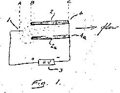
Fig. 1a is a chart Indicating the electric potential profile between the electrodes
of Fig. 1.
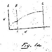
Fig. 2 is a diagrammatic view, partly in perspective, of a plural ity of electrodes
as set forth in Fig. 1.
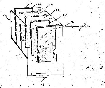
Fig. 3 is an alternate arrangement of electrode vanes providing
increased insulation and protection against accidental shock, together with a modulating
circuit for producing sound waves.
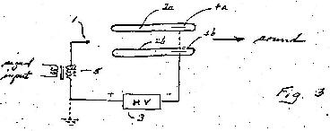
Fig. 4 is a similar device with a bare third electrode (control grid) for producing sound
waves.
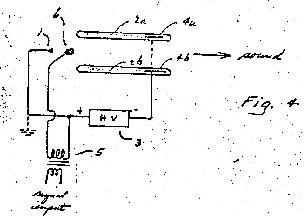
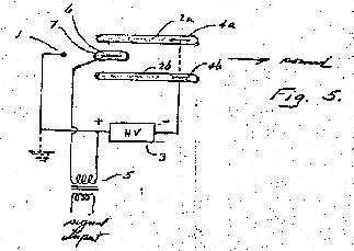
Fig. 5 is a device similar to that shown in Fig. 4 with the third electrode encased in
partially-conducting dielectric material.
 Referring in more Detail to the Attached Drawings:
Fig. 1 is a typical cross-section showing ionizing wire 1 associated with two
partially-conducting vanes 2 and 2a, terminated by metal strips 4 and 4a. Electrical potential
difference is supplied by direct current high voltage power supply 3. Electrode 1 is a fine-wire
equi-spaced between the leading edges of vanes 2 and 2a and extending longitudinally along and
near the (leading) edges of said vanes. It has been empirically determined that the location of
electrode 1, together with the loading edges of electrodes 2 and 2a, should form an equilateral
triangle, the size of which depends upon the voltage used. For normal operation, as an air fan,
the sides of the equilateral triangle may range from 1/4" for 10 KV to 1/2" for 20 KV. This
spacing is about one-half of the normal electric breackdown distance between metal points in
air at atmospheric pressure.
Because of the extremely high electric gradients developed, the ionizing envelope around
electrode 1 is intensified far beyond that which would be possible with naked metal electrodes.
It is this intensified ionization and electric gradient which results in increased air velocity
and sound pressure (when modulated). It is the principal feature of this invention. It
apparently is not covered in the prior art.
Fig. 1a is a graph showing the typical potential gradient found in the electrode-structure of
Fig. 1. If electrode 1 is considered to have zero potential of point A (this electrode may
actually be grounded in service without affecting the operation), the potential rises as B is
approached and then ranges still higher throughout the distance between B and C. The electric
gradient between A end C is therefore not uniform but is stepped, so that there actually exists
an electrical balancing action in the current passed between step A to B and step B to C. Any
excessive currentin step A to B instantly results in increased voltage in step B to C, so the
the current across the gap A to B is always balanced and limited. This limitation
effectively prevents breakdown.
In Fig. 2, a plurality of partially-conducting vanes 2a, 2b, 2c, 2d, and 2e are terminated with
metal electrodes 4a, 4b, 4c, 4d, and 4e, which are connected to the negative side of power supply
3. Fine-wire grid 1, with wires positioned intermediate and forward of the vanes, is connected
to the positive side of power supply 3.
It is to be noted that, whereas In Fig. 2 the fine-wire grid is made positive and the vanes
negative, the polarity may be reversed without reversing the airflow or affecting the sound
density. The reverse polarity does, however, produce an increase in ozone emission because of
the nature of the negative corona around the fine wires. Such corona is "beaded", with more or
less regularly spaced bright spots with high electrical gradient. The "spots" emit large
quantities of ozone. This characteristic has its advantage, however, in that when a larger
content of ozone is desired (in the effluent of the fan), the polarity may be reversed.
Fig. 3 Is similar to Fig. 1 except the the apparatus is utilized to produce sound rather than
merely the flow of air. Additionally, a shock-protective feature, is included by having the bare
metal electrodes 4a and 4b completely encased in partially-conducting material forming vanes 2a and
2b. This makes it possible to touch the vanes at any point on their surface without being
shocked. Fine wire electrode 1 is not so insulated but carries only the signal voltage from
modulation transformer 5 which is not dangerous to touch and is normally at ground potential.
In the absence of a signal. Variations in the potential of emitter 1 causes pressure waves which
travel largely In the direction of the vanes, passing between the vanes and outward as
indicated.
Fig. 4 is similar to Fig. 3 except that the field between the emitter 1 and vanes 2a and 2b is
altered by means of a control grid 6 according to the output of modulation transformer 5. This
electrode structure is similar to that disclosed in the applicant's co-pending Patent
Application 662,105, except that, in the present instance, the partially-conducting vanes 2a
and 2b completely enclose metal electrodes 4a and 4b and provide breakdown resistance and
protection against shock.
In Fig. 5, equivalent to Fig. 4, further breakdown protection is accomplished by encasing bare
control electrode 7 within its own partially-conducting sheath 6. Due to the fact that electrode
1 must have minimum surface am in order to produce maximum voltage gradient in the surrounding
envelope of air, it cannot be covered with insulating or semiconducting material. Such covering
would reduce the Ion emission from the region around electrode 1 and make the system virtually
inoperative. For protection against shock, however, such covering is not necessary inasmuch as
electrode 1 may be optionally grounded (as indicated). Grounding may be actually desirable in
order to minimize the insulation required in modulation transfoner 5.
The advantage to be gained by the use of partially-conducting material in the manner
specifically set forth in Figs. 4 and 5 constitute a basic improvement over the teachings of
Patent Application 662,105. In this respect, the present patent application may have to
provide this additional coverage as a "Continuation-In-Part" of Application 662,105.
The partlally-conductIng material referred to in this specification can be
fabricated in several ways. It may consist of phenolic plastlc (or the like) loaded with
carbon powder or metallic oxides. It may take the form of glass or plastic sheets with
thin metallic films deposited thereon. In certain cases when the precipitation vanes
must be made inexpensively such as for disposable precipitator sections, the vanes may
be made of metallized paper or a molded plastic covered with a thin film of stannous -
tetrachloride, to provide a limited amount of electrical conductivity.
It is important to distinguish in this patent application between the term "electrode" and the
term "partially-conducting vane". In the applicant's former patents, claims are made covering
the use of electrodes or sets of electrodes producing electrical fields between them. Breakdown
always occurred to limit the operating capability and it was never satisfactory to operate the
units even up to 70% of breakdown. The electrodes described in the applicant's issued patents and
forming the basis for those claims are now considered to be limiting. No device constructed
according to these earlier patents is free from the threat of damaging breakdown. The novelty
of the present application lies in:
It Is important, therefore, to stress in both the specifications and the claims of the present
invention the distinguishing feature which makes the present invention novel and useful over and
beyond the prior art. This distinguishing feature probably must be expressed as the
"partially-conducting vane" rather than the "electrode". It would seem that, by definition, an
electrode is a surface of uniform electrical potential. If that surface is not uniformly
conducting, the member ceases to be (strictly speaking) an electrode and becomes an element
of the electrical circuit, especially if its poor conductivity serves a useful purpose. Such
"elements" were not foreseen or taught in the earlier patented art. They provide the essential
feature of the present Invention.
The use of partially-conducting vanes serves still another purpose by increasing the resistivity
of electrostatically precipitated particles. Ordinarily, particles precipitated upon (dry) metal
electrodes suffer a certain amount of "bounce-off". Particles acquire the same polarity as the
electrode and are immediately repelled electrostatically.
When partially-conducting vanes are used, the electric gradient along the surface of the vanes
projects a divergent field outward from the sides of the vanes which reduces "bounce off" and
tends to trap and retain precipitates by dielectrophoretic attraction.


Please be advised that this document is copyrighted © by The Townsend Brown family. All rights reserved.
Please see Legal and Copyright Information for additional copyright information.
